technical

5637 steam locomotive group

Photo: Brian Haines

The principal and most visible components of 5637 are shown above

Pictorial views explaining the 5637 Driver and Fireman's controls

Photos: Paul Lockley

Annotations: Brian Haines

Working Practices

These 5637 working practices must be followed by host railways and all individuals operating the locomotive:

Footplate Crews' Duties and Responsibilities

No person may undertake footplate duties on the footplate of 5637 until they have been properly trained as either a Driver or Fireman. Both the Driver and Fireman must have successfully passed theoretical and practical examinations on the locomotive and all its systems. The level of these examinations will be determined by the 5637SLG, their advisors and the host railway’s Locomotive Superintendent or a person of similar authority.

The rostered Duty Driver is the responsible person in charge of the locomotive.

The Driver

Shall satisfy himself that all safety precautions are being observed at all times during his period of duty and that before entering the motion or going under the engine, the HANDBRAKE is ON, the cylinder drain cocks are in the open position, the Regulator is closed and the Reversing Lever is in mid-gear.

Shall read and observe all current notices, obtain any working instructions and any special instructions affecting 5637 or the running of the train.

Shall ensure that the Fireman is correctly attending to his duties.

Shall test the boiler water level for correct and safe levels and safe operation of the water gauge glass cocks.

Shall satisfy himself that within the firebox, the fusible plugs, tubes and stays are not leaking steam/water and that all the firebars and brickarch are in good order.

Shall satisfy himself that the injectors, the sanding gear, the steam heating system, whistles and the vacuum brake system are all in good working order.

Shall ensure that the locomotive and all its working parts are properly lubricated with the correct lubricant. Only superheater oil is to be used as cylinder lubricant. Refer to the Lubrication Procedure.

Shall, whilst carrying out the lubrication of the locomotive also inspect the working parts for any defects.

Shall report any defects found during his acceptance, lubrication and inspection of the engine. All defects must be entered in the LOCOMOTIVE MAINTENANCE LOG. If considered urgent a defect must be reported to the 5637SLG or the Locomotive Superintendent immediately.

Shall ensure that the locomotive has enough coal and water for the duty ahead.

Shall have with him, a full set of locomotive lamps, a set of tools, red and green flags and detonators (if the latter are deemed necessary).

Shall ensure that the locomotive displays the correct lamps at all times.

Shall ensure that the locomotive is correctly coupled to the train with the screw coupling, vacuum pipes and steam heating pipes.

Shall observe and obey all signals.

Shall keep a good lookout at all times, be fully aware of his and the locomotive’s circumstances. Ensure that the Fireman also keeps a good lookout.

Shall stop and start the locomotive and train safely with due regard to the weather, speed, size of train, day/night and rail condition.

Shall endeavour at all times to operate the locomotive in the most efficient and economical manner consistent with the work being performed, by good use of the Regulator and Reversing Gear.

Photo: Paul Lockley

The Water Level Gauge Glass

The Fireman

Shall on arriving at the engine ensure that the HANDBRAKE is ON.

Shall ensure that there is sufficient water showing in the boiler water level gauge glass. A minimum of one inch (1″) is required to be on show in the glass tube. The level is to be tested for accuracy by operating the water level gauge glass cocks.

Shall observe and obey all safety precautions and the Driver’s instructions.

Shall report any defects or problems to the Driver.

Prior to laying a fire on the grate, the Fireman must examine the firebox stays, tubes ends, firebars, brickarch and fusible plugs ensuring that they are all in good condition and showing no signs of leakage.

Before lighting the fire, the Fireman will ensure that the firebox is empty and the firebars are clean.

Whilst examining the smokebox, check for any signs of leaks or other defects. Ensure that the smokebox door is tightly secured shut.

Shall prepare and light the fire.

Shall ensure that the firebox air deflector plate is in good condition, is out of the firebox whilst the fire is being lit and prepared. To be refitted when there is sufficient steam pressure to operate the blower.

Once the blower is operating the Fireman shall clean out the smokebox.

Shall ensure that the lower firehole protection ring is serviceable and in position.

Shall ensure that the firebox ashpan dampers are fully operational and in good condition.

After any use of the blowdown vale and before moving off the Fireman shall clean out the ashpan.

Ensure that there is sufficient coal and water on the locomotive to enable steam to be raised to a working pressure.

Shall ensure that at all times, a full complement of fireman’s equipment is on the locomotive. This must include a firing shovel, a brush, a clinker shovel, a poker, and a dart, all to be in good condition.

Shall keep the footplate clean and tidy at all times.

Shall maintain a fire commensurate with the type of work expected from the engine. The fire is to be kept in good condition, with efficient burning of the coal, no black smoke.

Shall maintain the boiler pressure between 160 and 190 psi. It is permissible to lift the safety valves once during the working day to check they work at the correct pressure (200psi). To be confirmed by the boiler pressure gauge.

Shall in the absence of a shunter, couple/uncouple the locomotive to/from the train, ensuring that the screw coupling and vacuum pipes are correctly fitted. Fit the steam heating pipes as required in inclement weather (if instructed by the driver)

Shall, when the engine is working, assist the driver in keeping a good lookout, being aware of both the locomotive’s and his circumstances at all times.

Shall be prepared, in a case of emergency and in the absence of the driver take control of the locomotive and bring it to a safe halt in a safe place.

Photo: Jim Cobb

Fireman Linda Cowen on the footplate

lubrication 1

Lubrication systems and their requirements

It is the responsibility of the rostered duty Driver to ensure that all the lubrication systems are full and functioning. Any defects are to be reported to the 5637 SLG immediately. If in doubt ASK. To allow the maximum amount of oiling to take place in a degree of comfort, the locomotive should be stopped with the side rods left hand pins in the 9 o`clock position.

There are two basic systems on the locomotive:-

  1. Drip feed oil to the bearings, axleboxes, running machinery and slidebars.
  2. Pressure fed oil to the regulator and valves/cylinders.

Water Ingress

Rain water and condensate collects in all the oil pots, driving and trailing axleboxes. It can be measured in pints and therefore must be removed before oiling commences as any water in the sumps will give an erroneous full indication.

The front and rear main driving axlebox sumps (QTY 4 ) are fitted with 1/2″ BSP drain plugs, they must be removed to allow any water to run away prior to filling the relevant oil boxes.

To drain water from the centre driving axleboxes (QTY 2) a drainage device has been fitted at the bottom of the outer side rear of the axlebox, it sits between the wheel and the frames. It is a spring loaded device, held closed by the spring. To drain, push the centre plunger upwards using a thin piece of steel. Warning; the driving wheel balance weights will block access to one or the other of these drainage points and the driver will have to wait until steam is raised to move the engine or the services of another locomotive used.

Rear trailing pony truck axleboxes. Remove the cork located at the bottom rear outside of the axlebox and siphon out any water.

A variety of oil pots are situated on the reversing mechanism, the slide bars and to lubricate the valve/piston rods. Provided they are kept covered by tin cans no water should enter them but if it is suspected that water contamination is present then it must be siphoned out.

Big ends, eccentrics, side rods and valve gear. These oiling points are always sealed with corks but if water ingress is suspected then it must be siphoned out.

Gravity/Drip Feed Lubrication

Lubricant:- Locomotive Bearing Oil

External Points

Rear Trailing Pony Truck

Qty 2 axleboxes; filled from two points on top of each axlebox, sealed by corks.

A small quantity of oil is to be poured down the pony truck horn guides at the four corners.

Rear Driving Axle

Two four feed oil boxes, left and right hand, are secured to the rear of the water tanks in the cab. All four wells must be filled in each box. Each well to possess a wick trimming.

Photo: Paul Lockley

Rear Driving Axle Oil Box

Front Driving Axle

Two four feed oil boxes are secured to the front left and right hand splashers. All four wells in each box must be full and each well to possess a wick trimming.

Photo: Paul Lockley

Front Driving Axle Oil Box

Centre Driving Axle

These oiling points are located on top of the left and right hand axleboxes between the frames and the driving wheel. Oil is poured down a stack pipe. Caution, do not force corks down the pipe to act as a blank. They are difficult to remove. Warning; The driving wheel balance weights can block access to the oiling stack pipes, the driver must move the locomotive at some point to gain access to one or the other. The driver must therefore remember to ensure that the unfilled oiling point is filled before the engine commences work. It is at this time that the water can be drained from the axle sump.

Side Rods

There are six oiling points, one per driving wheel. No wick trimmings are used. A splash of oil on the inner and outer faces of the bearings.

Photo: Paul Lockley

Side Rod Oiling Point with Cork in Place

Brake Rigging

Each brake block hanger (QTY 6) requires a splash of oil on the top and bottom pins, plus a splash at the brake block attachment point.

Photo: Paul Lockley

Brake block pins

A splash of oil to be applied to the various pins that secure the brake rigging under the engine.

The brake cross shaft under the vacuum brake cylinder has two oiling points at each outer end.

Spring Hangers

A splash of oil onto the spring hanger pins. Total 16 for all axles.

Centre Axle Box Horn Guides

Two lubricating boxes, one each on the top centre of each water tank. These only supply oil to the hornguides, not the main bearings.

Photo: Paul Lockley

Central Axle Hornguides Oil Box.

Reversing Lever

A splash of oil is to be applied to all the movement pins on the Reversing Lever in the cab.

Hand Brake

Oil is to be applied to the hand brake upper support and the lower screw thread plus associated pins and bearings.

Injector Water Handles

A splash of oil on each upper support bearing.

Sanding Mechanism

Two sets, operated from the cab. Right hand system operates the front sanding boxes. The left hand system operates the rear sanding boxes. All pins and bearings from front to rear to be oiled.

Vacuum Pump Pot

This is located on the front of the right hand water tank. To prevent the vacuum pump swiftly sucking all the oil out, the pot is filled with woollen waste, this absorbs the oil and the pump when working, then extracts an oil mist.

Photo: Paul Lockley

Vacuum Pump Oil Pot.

Between The Frames

Big Ends

Left and right hand located on the centre driving axle. No oil feed trimmings fitted. Blanked off by corks.

Photo: Paul Lockley

Big End Oiling Point.

Eccentrics

Qty 4; located in the centre of the centre driving axle between the two big ends. No oil feed trimmings fitted and blanked off by corks.

Photo: Paul Lockley

Eccentrics Oiling Points.

Reversing Mechanism & Links

Qty 10;  points, blanked by small corks with oil feed trimmings. The faces of the expansion links to be well oiled as are all the various hinge and supporting pins. The reversing cross shaft has two oil pots at either end. The reversing reach rod is supported in the centre of its travel by a radius slot, this to be oiled, plus the pin where it is secured to the reversing cross shaft requires oiling.

Photo: Paul Lockley

Reversing Mechanism Oiling Points & Cross Shaft Oiling Pot.

Vacuum Pump

Splash oil onto the pump piston rod.

Piston Valve Rods

Two pots with wick trimmings, one per rod. Also splash oil on rod and into the felt pads at the gland packing.

Photo: Paul Lockley

Piston Valve Rod Oil Pot.

Slide Bars

Three oil pots per set of slide bars located on the upper centre bar, each pot has a wick trimming. The front pot lubricates the main piston rod. The centre pot supplies oil to the sides of the slide bars and the rear pot, oil to the underneath centre of the top bar and therefore top centre of the crosshead. Splash oil onto the lower slide bars.

Photo: Paul Lockley

Slide Bars Oil Pots.

Crossheads

Each crosshead has five oiling wells. The wells at the front and rear supply oil onto the top of the two lower slide bars. The single centre well supplies oil into the little end pin. Splash oil down the sides of the cross heads.

Main Piston Rods

Apply a liberal coating of oil onto each piston rod and into the felt pads at the gland packing.

Pressure Fed Oil

Lubricant:- Superheat Steam Oil

Warning. This oil is fed to the regulator, piston valves and cylinders under steam pressure supplied directly from the boiler and therefore the system must be considered hazardous with a high risk to the footplate crew if handled incorrectly.

To operate this system, direct boiler steam is supplied via two “J” cocks from the Manifold, both are to be selected “ON” in normal use. Steam goes straight to the Jockey Valve below the regulator. The water used to force feed the oil into the engine is derived from a condenser coil bolted to the roof. This coil receives its steam from a “3-Way Y” valve on the top of the Manifold. This valve is to have both legs open to boiler steam. The water enters the Hydrostatic Lubricator body via a “3-Way” valve. Selected in the centre, the valve is CLOSED and no water passes. The handle can be moved either left or right to OPEN a port and allow water at boiler pressure into the lubricator. It is therefore important to ensure that this valve handle is centred before removing the filler cap.

Superheat steam oil is very thick and must be warmed up before it will pour easily.

Photo: Paul Lockley

Hydrostatic Lubricator

To Fill The Hydrostatic Lubricator

This is best carried out when there is no pressure in the boiler. Place lubricator “3-Way” Valve in CENTRE CLOSED position. If pressure exists, then ensure that the lubricator is isolated from the supply of high pressure steam and water. To check if the lubricator is under pressure, gently crack open the filler cap by two threads, if pressure exists then its presence will soon be noted. To cut off any source of pressure, close both the Manifold “J” cocks and the “3-Way Y” valve. Allow the pressure to dissipate to zero.

Open the Lubricator lower water drain valve, allow all the water to run to waste. Close valve.

Remove filler cap and pour in the lubricating oil till full. Refit filler cap and tighten into place.

If the Manifold “J” cocks and “3-Way Y” valve have been closed, now reopen slowly.

Operating The System

Just before moving off.

Place the Lubricator “3-Way” valve into one of the OPEN positions

OPEN the oil delivery valve on the Lubricator lower distribution manifold.

OPEN half a turn the three supply valves on the bottom of the lower distribution manifold. One to the regulator, two to the valves and cylinders.

Regulate all three oil flows at four (4) drops per minute. Do not allow the flow to exceed this as the system may become choked with oil. To be constantly monitored by the driver.

Oil Blockages

Ensure no pressure is present in the Lubricator body as described earlier.

Slowly remove the gauge glass upper steel blanking plug. Using a thin piece of wood with a strip of cloth attached, soak up the surplus oil. When gauge glass clean, refit steel plug and retighten. Reapply pressure and proceed.

locomotive maintenance

Locomotive maintenance can be split into two major parts:-

  1. Boiler and pressure fittings, maintenance and repair
  2. Mechanical maintenance and repair

Both these types of maintenance must be carried out by people who are deemed COMPETENT by the 5637 SLG and the host railway. A definition of a competent person is :-

This is a person who by either theoretical or practical training has the necessary ability and skills to carry out both boiler and mechanical steam locomotive maintenance and repair work in a safe manner. They will have the proper skills to identify any hazards/defects present, determine the risks they present to the workforce and the public. They will be able to make the correct and safe decisions based on their level of training and experience.

It is the 5637 SLG and host railway’s duty to ensure that a person is competent and fully authorised to carry out any work on 5637.

Photo: Chris Perkins

Barney and Matt carry out a boiler washout

A “MAINTENANCE LOG BOOK” has been created and must be used to log any work of any type being carried out on 5637 irrespective of how serious or trivial that work is deemed.

Typically, the LOG BOOK headings will be:-

  1. Date.
  2. Fault or maintenance activity or “non” as the case may be.
  3. Diagnosis of the defect and investigative comments.
  4. The work carried out to render 5637 serviceable.
  5. Tradesman and supervisor. Printed names and signatures required.
  6. Independent 3rd party safety check required on all boiler work, live steam fittings and locomotive brake systems and component parts. Printed name and signature required.
  7. Does the fault/repair/ maintenance activity require a period of observation with the engine in service before being declared fully serviceable. If this is the case, what are the reasons and has the matter been made known to the Driver or other responsible person. Are their observations and comments required? To be declared SERVICEABLE by a competent person.
  8. Completion date

The Duty Driver will, on commencing his turn of duty, be advised of any outstanding repairs/defects or investigations and if required be asked to monitor and report back on them. On the cessation of his turn of duty, the off-going driver will either advise the new driver of any problems or place in writing in the MAINTENANCE LOG BOOK any defects/problems/comments encountered during his turn of duty. It is a requirement that the off-going driver must make comment in the log book even if only to state “NO FAULTS OR DEFECTS NOTED”.

Boiler and Live Steam Fittings

A safety procedure has been published for this type of work. It must be adhered to at all times. Do not start work until this procedure has been read and understood.

Mechanical Work

The people carrying out this work must have a skill level commensurate with the work being demanded of them, i.e. are they competent to do the work. Managers and supervisors must ensure the correct person is allocated the right type of work and exercise a proper level of supervision. Mechanical work covers a wide spectrum of activity across a variety of engineering disciplines.

All mechanical work must be of high standard with good locking/security practices and finish.

On completion of all types of work, 5637 must be in a fit and safe condition to work on the railway.

boiler washout

Boiler Washout Plugs, Mudhole Doors and Live Steam Fittings

Fitting / Removal Procedure

WARNING


Before commencing work on the boiler, ensure that there is no pressure within the boiler by referring to the boiler pressure gauge first, then opening the regulator or injector steam supply valves. Before removing any plugs or mudhole doors ensure the boiler water is COLD, this will prevent scalding from the draining water.

If In Doubt Do Not Proceed Ask For Advise Or Assistance.

  1. Only those persons authorised by the 5637 Steam Locomotive Group, the Railway and those whose names are held in a register may fit or remove the washout plugs and mudhole doors to the boiler. There are to be no exceptions.
  2. An authorised person is one who is deemed competent to fit/remove boiler washout plugs and mudhole doors. A competent person is one who fulfils the following criteria:-
    • This is a person who by either theoretical or practical training has the necessary ability to safely fit/remove both boiler washout plugs and mudhole doors. They have the proper skills to identify any hazards present, determine the risks they represent to the workforce and the public and make the correct decisions based on their level of training and experience.
  3. It is the Railway Management`s duty to ensure that a person is competent and therefore properly authorised. The Management has a duty to ensure that a competent person has the right level of competency to undertake the tasks of safely fitting/removing boiler washout plugs and mudhole doors before authorising them.

Boiler Washout Plugs (Qty 39)

  1. Prior to fitting, all the washout out plugs must be scrupulously cleaned, especially the threads and heads. The threads of the washout plugs are to be coated with suitable sealant such as Foliac or Stag.
  2. The washout plugs must be fitted in sequence as shown on the supplied boiler map, this ensures that the correct size plug is fitted into its proper threaded hole.
    • Due to the taper of the plugs, care must be taken to ensure that they have been correctly fitted and not cross threaded. The plugs are to be screwed in by hand until they can go no further, then a spanner used to achieve the final tightening.
  3. When all the plugs have been securely fitted into the boiler, they must have a second independent check by a competent person. This is an independent means of ensuring that all is well and that all the washout plugs are properly secured in their rightful position.
  4. Should a leak be noted from a washout plug, no attempt must be made to tighten the affected plug. The fire must be dropped, the boiler cooled down and the pressure dissipated to zero before any rectification can commence. To avoid any pressure, it is advisable to fully open the regulator or injector steam valves.

Boiler washout plug and mudhole door locations

Mudhole Doors

  1. There are eight (8) mudhole doors:-
    • one at the firebox rear bottom backplate
    • four on the upper curves of the firebox crown sides
    • one in the firebox front plate
    • one in the left hand corner front plate
    • one in the right hand corner front plate†

Prior to fitting the mudhole doors, the doors must be scrupulously cleaned and the matching inner surfaces of the of the mudhole door apertures in the boiler plate must also be cleaned. All to be free old gasket and sealant material.

  1. On fitting each door a new seal/gasket must be fitted, no old ones are to be reused. Sealant such as Foliac or Stag should be applied to each side of the seal.
    The Fitter must ensure that the door is squarely and evenly located in its aperture before finally tightening the securing nut.
  2. Should a leak be noted from a mudhole door no attempt must be made to tighten the door securing nut, the fire is to be dropped, the boiler cooled and all pressure dissipated to zero before any rectification commences. As a safety precaution it is advisable to fully open the regulator or the injector steam valves.

Boiler washout plug and mudhole door locations

Live Steam Fittings

  1. Only to be removed and fitted by authorised and competent persons as described in paras one to three (1 – 3)
  2. If a live steam fitting is to be removed from the boiler which contains a fire or steam pressure, then the fitting must only be removed if it is safely isolated from any source of pressure. Isolation will usually be via a nearby cock, valve or tap. If the fitting cannot be isolated, then the boiler must be made safe and all pressure dissipated to zero. Beware of scalding water, even if no pressure is shown to exist, it can be held inside the fitting.
  3. To fit a live steam fitting, always ensure the isolation system is still protecting the system or fitting concerned. Use Foliac or Stag on any threaded component or pipework. Carry out a functional and leak check to ascertain if the fitting is now serviceable. If it is not, carry out any further rectification as necessary with due regard to para (12).

frost precautions and water drainage

To prevent damage to many of the pipes and fittings that may accumulate water or condensate at their lowest point, several have been fitted with drain plugs.

Prior to winter conditions setting in, these plugs must be removed.

Their locations are as follows:-

  1. Qty. 2, washout plugs, one each, screwed into the bottom of the each side tank above and adjoining the rear driving wheel/ rear sand box.
  2. Qty. 2, 3/8î” BSP plugs, one each in the bottom curve of the injector to clack delivery pipes, where the pipes turn up into the side tanks.
  3. Qty. 2, 2.5″ BSP iron plugs, screwed in to the bottom rear of the balance pipes twixt coal bunker and side tank. Left & right hand sides.
  4. Qty 2, 1/4″ BSP plugs, located in the bottom of the curve of the steel portion of the injector live steam down supply pipe. Left & right hand pipes.
  5. Qty 2, 1.5″ BSP iron plugs, located at the bottom rear of the injector water supply pipes as they exit the water space of the coal bunker.
  6. Qty 1, 3/4″ BSP plug, in the steam heat piping below the coal bunker, right hand side forward.

Photo: Paul Lockley

Water drain plug in balance pipe

modification list

Modification List for Steam Boiler Assembly and Associated Fittings

No person is to carry out any modification to the steam boiler assembly and associated fittings unless that modification is fully described in writing with supporting drawings and has been approved in writing by the Insurance Company Boiler Inspector. Any modification being carried out must only be incorporated by a Competent Person. Any welding to be carried out, must be done by an Insurance Company approved welder with the proper skills and qualifications.

Before any Modifications are carried out it is essential that the persons involved have read and understood the following procedure:-

“Boiler Washout Plugs, Mudhole Doors and Live Steam Fittings – Fitting/Removal Procedure”

All modifications made must be recorded in the Modification List which can be downloaded from HERE.

Photo: : Steve Masters

Jeff welding inside the boiler barrel

risk assessment

This Risk Assessment concerns the steam locomotive number 5637, an ex-Great Western and British Railways 0-6-2 tank engine. Built during 1925 at the Swindon Railway Works.

The Risk Assessment applies to the Railway where the locomotive is currently located.

The hazards associated with this steam locomotive are listed below:

  1. Scalding of the body from steam and boiling water.
  2. Hot burns to the body from the fire, pipework and fittings.
  3. Falls from height.
  4. Crushing from the locomotive`s machinery.
  5. Asphyxiation from smoke fumes.
  6. People being run over by the locomotive.
  7. Exploding boiler.
  8. Confined spaces.

All of the above can be fatal or inflict a very serious injury to a person.

Listed below are the steps to be taken to reduce each of the above hazards to an acceptable LOW RISK.

General Comments For All Eight Hazards

No person must be rostered as a member of the footplate crew, i.e. Driver, Fireman or Trainee Fireman unless they have undergone a period of familiarity training on the locomotive, its equipment and operating systems. Each person must be fully trained for the role they undertake and be certified as “COMPETENT” by the Railway’s Locomotive Superintendent. This certification must be placed in writing and recorded on official paperwork. Refer to “Footplate Crews” Duties and Responsibilitiesî dated 15 July 2010.

No person must undertake any form of Examination, Inspection, Maintenance or Fault diagnosis unless they have been certified as competent to do so. Refer to “Locomotive Maintenance” dated 15 July 2010.

Having undertaken a course of training, each person must be able to understand the hazards of the locomotive and reduce the risks to themselves and others to a low and safe level.

  1. Scalding of the body from steam and hot water

As stated all members of the footplate crew must have undergone a suitable training course on how to operate the locomotive controls and systems.

They must be aware of the hazards associated with waste steam escaping from the injector overflow pipe affecting people on the engine steps or at ground level, making sure no one is in a position to suffer any form of injury from steam, hot water, noise and physical reaction.

Photo: Paul Lockley

Injector Overflow Pipe

They must be aware of the hazards associated with steam escaping from the cylinder drain cocks. They must make sure no one is in the vicinity of the cocks when steam is applied to the cylinders with the cocks open. There is danger from the hot steam, noise and track debris being thrown at high velocity into the air.

Using the cab slacker pipe to wash the cab floor, the operator must not direct the jet onto any person but only onto the floor or the coal in the bunker. Beware of splashing outside the cab and spraying hot water onto those nearby.

Operating the water level gauge glass try-cocks to determine the level of the boiler water. Ensure that no one is forward of the cocks. Scalding will occur if skin contact is made.

Operating the locomotive steam heating system. Those coupling/uncoupling the engine system to and from the coaches will suffer scalding from steam and hot water should the system be pressurised. The steam supply valve on the manifold must be fully closed and no pressure showing on the system pressure gauge. The operator should wear protective gloves and depress the pipe joint drain valves to ascertain no pressure or hot water is in the system. The footplate crew must be aware at all times that staff are working on the steam heat piping.

There is a hazard present when replenishing the pressurised cylinder and regulator oil reservoir. The reservoir must be isolated from any source of pressure before removing the filler cap. Isolation is achieved by placing the 3-Way valve in the centre closed position and gently opening the filler cap two revolutions to allow any residual pressure to escape. Should this prove ineffective then the two manifold “J” cocks and the condenser 3-way valves must be closed before proceeding further. Refer to “Lubrication Systems and their Requirements” dated 15 July 2010.

All maintenance, examinations and inspections must be carried out only by trained and experienced members of the engineering staff who must be accepted as competent to carry out the work. Read “Locomotive Maintenance” dated 15 July 2010 and “Boiler Washout Plugs, Mudhole Doors and Live Steam Fittings – Fitting/Removal Procedure” dated 15 July 2010.

No boiler or live steam fitting must be removed or worked on, other than in its intended capacity, when the boiler is hot or under pressure. The boiler must be cold and unpressurised, with the regulator in the open position and the pressure gauge reading zero. However, some systems can be isolated from the boiler. Before commencing work on any live steam fitting associated with a hot boiler and known to be under pressure, the responsible person must ensure the fitting and associated pipelines are fully isolated from the boiler and do not contain any pressure, steam or hot water. Break any unions very carefully and slowly.

  1. Hot burns to the body from the fire, pipework and fittings

All members of the footplate crew and maintenance personnel must be made aware of those items which can burn parts of the body. All piping and fittings in the cab must be considered a hazard, all contain steam or water at boiler pressure and temperature. To be handled with protective gloves or rags.

The heat that can escape from a large fire when the firehole doors are open is excessive and will cause damage. With the blower shut OFF, large gusts of heat, flame and smoke can suddenly escape from the firebox when the firehole doors are opened. Therefore, were ever possible the blower must be in use to draw the fire down the tubes into the smokebox. If no steam is being created to enable the blower to be used, then great care must be taken when opening the firehole doors. The operator must wear suitable protective clothing such as gloves and overalls, stand well back and using the door handle open the doors slowly. The doors must be closed as soon as the reason for opening them has been satisfied.

On the right hand side of the locomotive the steam heating supply pipe to the front hose is located at running board level. The footplate crew must warn those on the ground near the pipe to be aware of the hazards.

Whilst insulating cladding is fitted around the boiler, the firebox area is very hot and can cause dry burns to those who for any reason need to be on top of the boiler. Should anyone have a need to go on top, then suitable heavy protective blanketing must be used as a source of protection from the heat. Shock reaction can cause people to fall to the ground.

  1. Falls from height

To fill the water tanks, the footplate crew have to climb onto the tank and open the tank lids. They are to use the proper steps and handrails making sure their footwear and gloves/hand are clean, to enable a safe grip and safe foot position to be achieved.

Photo: Paul Lockley

Water Tank Lid

Working on top of the locomotive when it is hot can cause people to fall through shock reaction. Insulation blankets and protective gloves/clothing must be used.

People must only go onto the top of a hot boiler when it is essential to do so.

When the coal bunker is full, there is a danger of any occupant falling to the ground due to the instability of the coal. Personnel must be aware of this and use the cab as a means of support.

Due to the amount of protrusions, tools and fittings on the water tank tops, trip hazards exist with associated falls to the ground. Only personnel on essential tasks are to transit the water tanks and then with caution.

Both the boiler and tank tops can become greasy when wet, clean footwear must be used and personnel are to proceed with caution.

  1. Crushing From The Locomotive`s Machinery

Whenever, any person, irrespective of the task, is working on the locomotive, other than when the locomotive is meant to be moving, the handbrake must be in the ON position. This may be supplemented by the engine vacuum brake or the engine properly secured to another rail vehicle with an operational working handbrake in the ON position, (should work be needed on the handbrake itself.)

If other engines and vehicles are moving on the railway, then no one must go under or into the engine unless the engine is protected by being on a piece of track isolated from the rest of the system by points being set to divert any other moving vehicle away from the locomotive.

If members of the footplate crew are oiling the engine, then their fellow crew members must be made aware of their location and act as guard/safety man.

No one must go between the locomotive and any other vehicle until the locomotive has stopped, brakes applied and authorised by the Driver. They must enter between the vehicles in full view of the Driver, ensuring he is fully aware of their intentions.

Photo: Jim Cobb

Driver John Greathead coupling up

  1. Asphyxiation from smoke fumes

A steam locomotive by its very nature due to burning coal, creates smoke. To prevent smoke entering the cab or other working spaces the blower must be ON. If this is not possible, all the cab doors and windows must be open to allow fresh air to enter the cab. Smoke fumes contain a variety of noxious elements of which carbon monoxide is but one. These fumes can cause a lack of concentration and rational thought. It is possible that people can be overcome by fumes and perish.

  1. People being run over by the locomotive

The Driver, assisted by other crew members must ensure the track, in the direction of movement, is clear of people, materials and litter.

To warn people of engine movements, the whistle must be sounded. If people do not move to safety and respond to the whistle, the Driver shall not proceed until the track is clear.

People operating in and around the locomotive must make their presence and intentions known to the Driver and acknowledge any signals or whistling in a positive and recognisable manner.

  1. Exploding boiler

This is always fatal to those nearby.

Boilers, fail and explode due to structural failure brought about by neglect or very rarely, component failure.

To prevent this happening the boiler will undergo at regular time periods examinations and inspections by competent persons, who will determine the condition of the boiler and its associated fittings. Any faults or defects will be acted upon and the boiler kept in a serviceable condition. Refer to the current †ìWritten Scheme of Examinationî for this boiler.

Low water levels in the boiler will cause the boiler to fail, the water absorbs the heat of the fire, preventing the firebox from overheating and therefore collapsing causing an explosion. It is essential at all times when a fire is on the grate that water is showing in the water level gauge glass.

To ensure that water is in full view at all times, the footplate crew must ensure that both injectors are fully serviceable and that they feed water into the boiler and that the water level gauge glass is accurately reading the water level. Should any of these items be found to be unserviceable and the true level of the water becomes uncertain or disappears out of sight in the gauge glass, then as a matter of urgency the fire must be removed from the firebox or extinguished immediately.

Should a firetube or superheater element fail this will also create a similar situation to an exploding boiler, causing death or serious injury to those nearby. An escape of high pressure steam from these tubes will drastically upset the steaming of the engine, normally destroying the smokebox vacuum and blowing the fire off the grate into the cab area. Both the driver and fireman, on starting their turn of duty must examine all tube ends in both the firebox and smokebox for either water or steam leaks. Should any be noticed, they are to be reported to their immediate superior.

  1. Confined Spaces.

Do not enter the two water side tanks or the coal bunker water tank unless they are empty of water, well ventilated by fresh air by having all their panels and filling/drain points open. A second person must act as safetyman, being of a physical size to be able to enter the tanks and render assistance if necessary. Adequate lighting must be provided.

Do not enter the firebox unless the boiler is cold and all the ash and fire debris has been cleaned from the grate. The firehole doors must be open at all times, as must the ashpan damper doors. Adequate lighting must be provided and a safetyman present.

Do not enter the smokebox if the fire is lit, smoke is present in dense quantities, unless it is necessary to carry out any functional checks. Good lighting is essential as is a safetyman. Wear protective overalls and gloves. Hot surfaces abound. Remove the door retaining bar for easy access and exit.

Photo: Chris Hopkins

Alex squeezing into the inspection hole in the bunker water tank

operating instructions

Filling or Topping Up the Boiler

5637 is equipped with a firehose attachment on the driver’s side injector overflow pipe. To top up the boiler, simply attach a firehose and turn on. Water should enter the boiler via the top feed. You may need to open the regulator to let the displaced air out of the boiler. There should be no need to remove any boiler plugs or mudhole doors.

Warming the Boiler

If the loco has not been in use, a small warming fire must be lit under the brick arch the day before it is to be lit up, with the aim of bringing the temperature up over the course of approximately 3 hours to a point where it is just too hot to hold your hand on a boiler plug on the back head.

Lighting Up

The boiler should be hot from either the running or the warming fire the day before. Steam should be raised in a steady manner. The blower should be used sparingly i.e. just sufficient to stop the fire blowing back into the cab. The blower should be regularly reduced as the pressure increases to avoid steam being raised too quickly.

The ashpan should be checked and cleaned if required. Note that the rear half of the ashpan slopes up under the grate. This needs to be kept clear of ash daily otherwise the firebars will be damaged and the fire will not burn correctly. When emptying the ashpan, a hose should be used to dampen down the ash to stop it flying up and sticking to the motion. Great care should be taken not to spray any firebars or any part of the boiler with cold water.

Cleaning

The paintwork should be cleaned with an oil / paraffin mix. Copper pipes, the chimney cap and the brass work should be cleaned with metal polish.

Driver’s Preparation

The loco should be subjected to a routine fitness to run examination at the start of every day.

Most oil points are in the obvious places but there are some hidden ones! See: Lubrication Systems and Their Requirments.

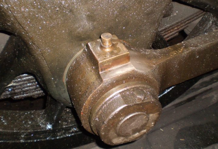
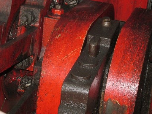
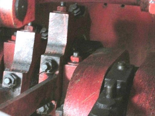
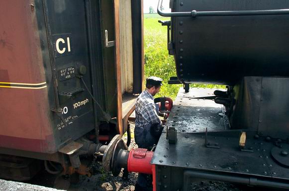
The best position for oiling up is with the coupling rods at the bottom centre on the driver’s side. Most oil pots can be reached in this position and there is room to climb up over the big ends. The loco will need to be moved into other positions to gain access to the axle boxes though.

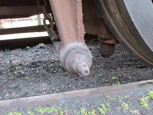
Leading and trailing axle boxes should have any water drained daily via the drain plugs and topped up via the cork in the under keeps from under the loco.

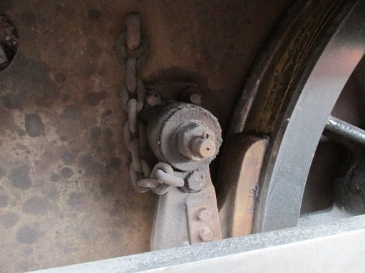
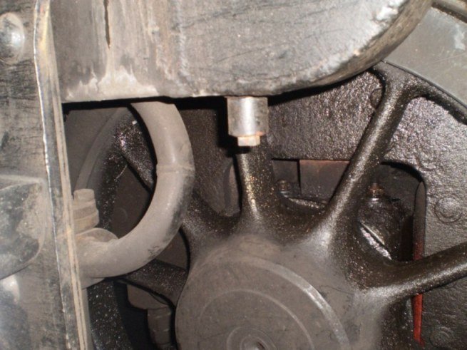
The centre driving axle boxes have the under keeps filled via a cork which can be found from the outside, to the rear of the axle box, between the wheels and the frames. As this feeds the under keep via a relatively small hole, it can appear full of oil when it is not. Allow the oil to run through and the level will drop. You should expect to put around 1 pint of oil in each per day. There are also spring loaded drains below the filling points on these two boxes but it is rare that water is found in these. To drain, lift spring loaded plunger adjacent to the cork.

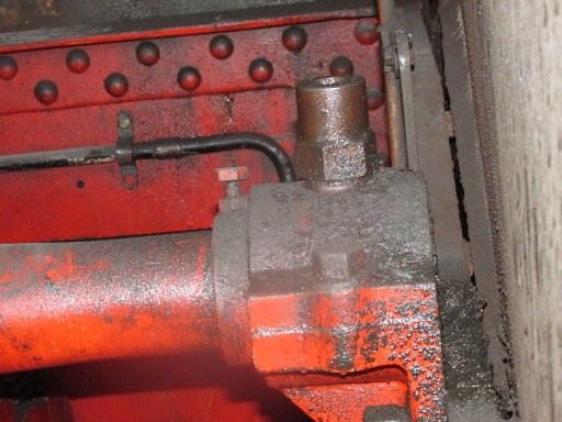
Also on the centre driving boxes is a small pipe rising up out of the top of the box between the wheel and the frame. This feeds the top well in the axle box which in turn feeds the horn faces. Remove the cork and top up with oil. It is likely that the loco will need to be moved to gain access to some of these.

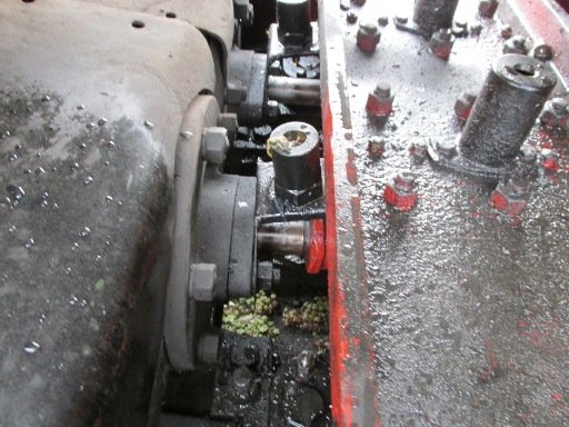
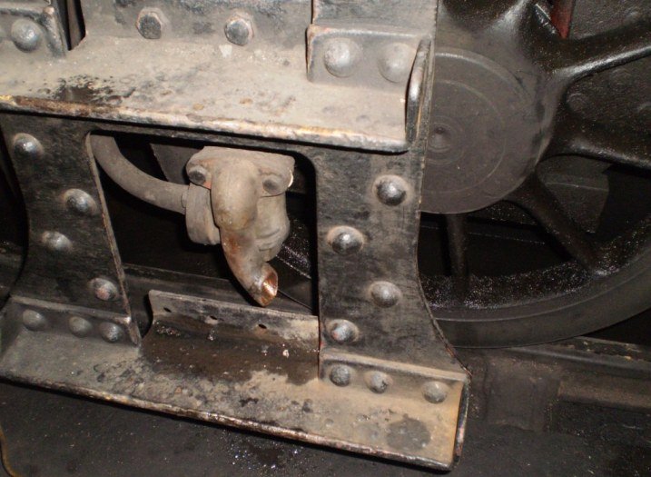
The radial truck has two corks on the top of the casting just inside the wheels each side. These feed directly onto the crown of the bearings and from there, any oil simply runs into the under keeps, so it is not possible to fill them completely. Aim to put approximately 1 pint into each and then top up the under keep via the cork at the lower rear edge. Also run oil down behind the wheel between the wheel and the thrust faces.

Any oil pots found to be full already should be checked for water and the condition of the trimmings inspected to find the cause. Any water found in any oil pots should be removed.

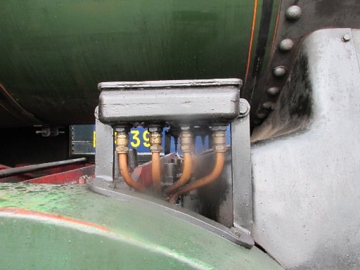
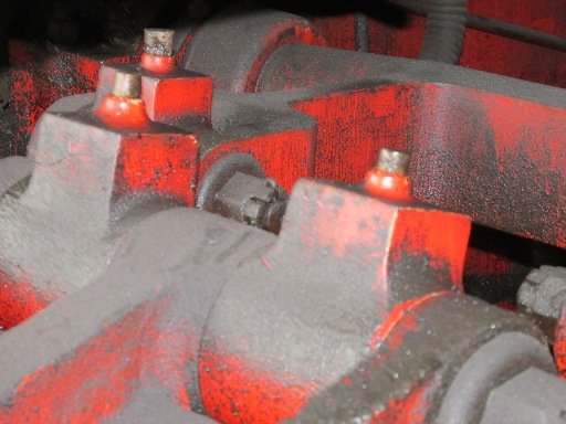
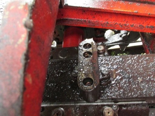
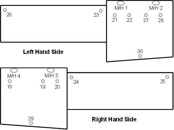
On the top of the crossheads are 5 corks, 2 on one side and 3 on the other. Note that each side is a common oil chamber and so as long as one filling point is filled each side of the crosshead, that should be sufficient.

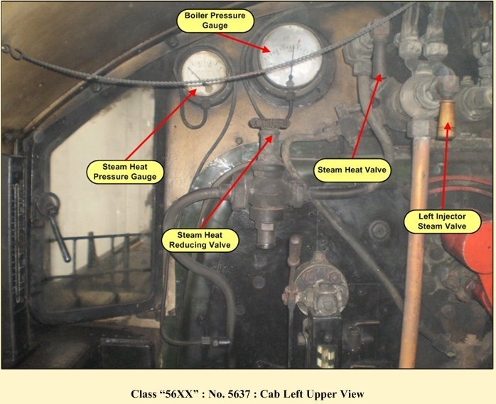
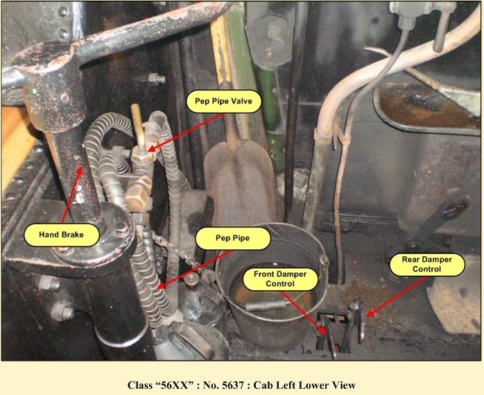
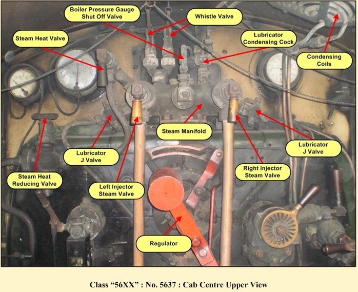
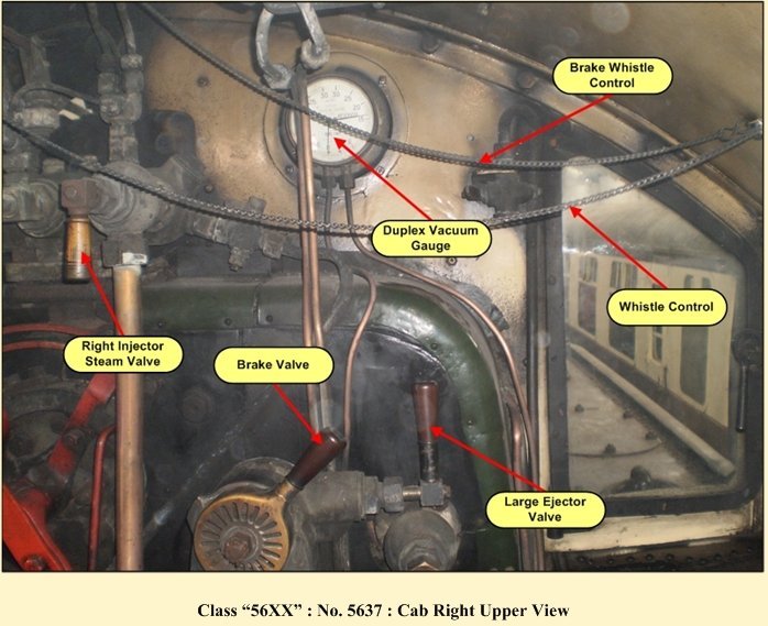
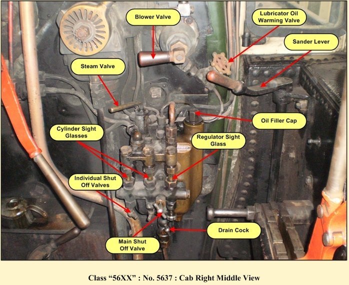
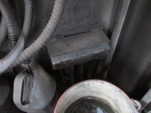
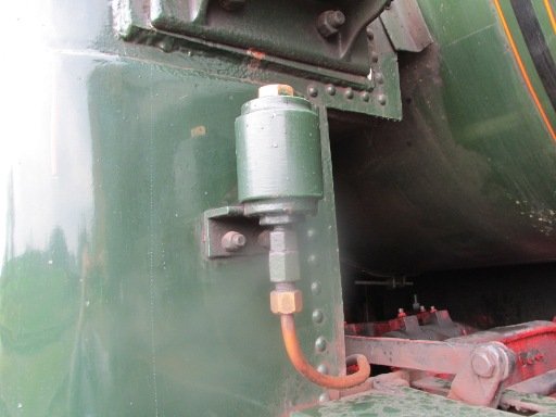
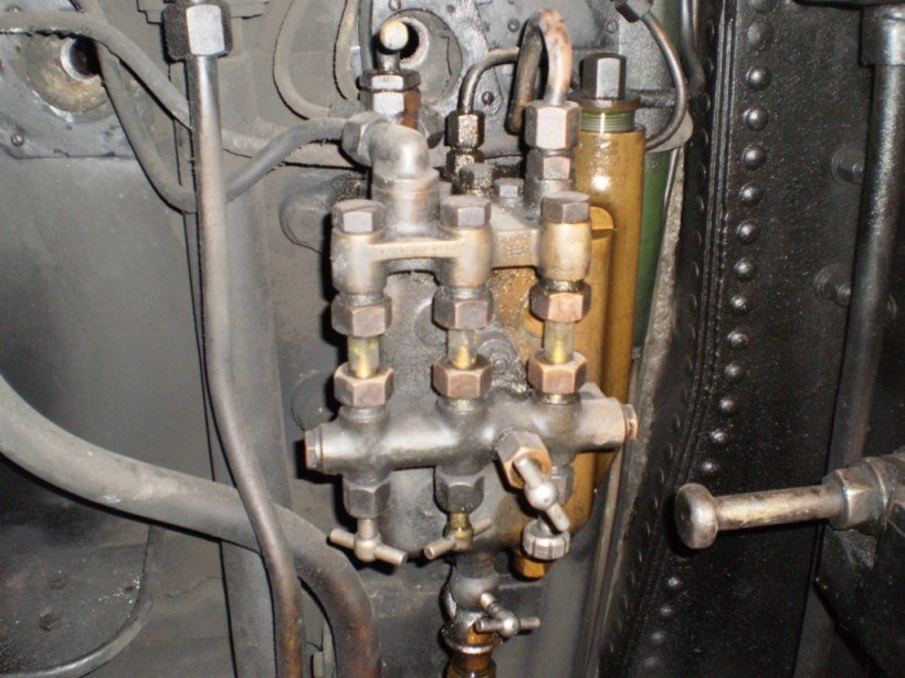
The lubricator in the cab should remain turned off until it has been drained of water and filled with oil. To do this, first check that the steam / water supply from the condenser coils is turned off. This is with the main valve pointing straight out towards you. Open the drain valve at the bottom of the unit. A small amount of water should trickle out but not under pressure. If water is coming out under pressure, do not remove filling plug until it has stopped. Remove the filling plug and the oil level should then fall as the water runs out of the drain valve. Continue draining until only oil is coming out and then close drain valve. Top up to the top with steam oil suitable for superheated locos. Refit the filling plug and turn on the lubricator by turning the handle 45 degrees either to the left or the right. Normally the feeds in the three sight glasses remain set and just the common rail isolator is turned off when not in use. However, adjust the feeds if required so that they are feeding at a rate of 2-3 drops per minute in all three glasses  this is usually just 1/8 to1/4 of a turn from the closed position.

If it is a particularly cold day, there is a heater valve for the lubricator which can be used. This should only be used if the oil will not feed.

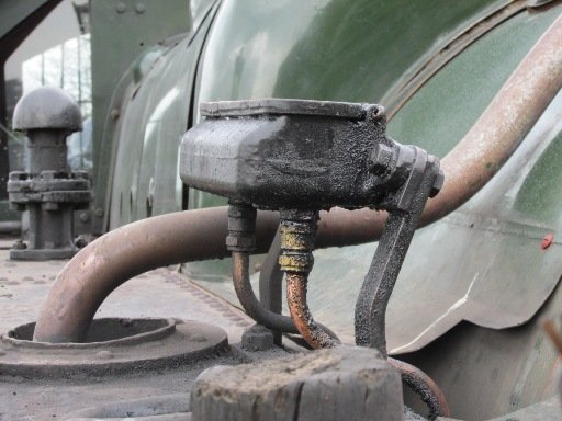
The vacuum pump oil pot can be filled with normal lubricating oil or a 50/50 mix of lubrication oil and paraffin in colder weather.

Firing

Allowing holes to form over any portion of the grate is to be avoided. The boiler pressure should be regulated by correct use of the dampers and good management of the fire.

The injectors are very reliable and easy to operate. With the water turned on, steam on, regulate the water valve until the injector picks up and runs dry.

The deflector plate should be in place at all times the loco is in use.

Driving

Vacuum Brakes – the driver should initially create the vacuum using the ejector. The loco should not be moved until the reservoir side of the vac gauge has reached its maximum 23″. On the move, the ejector can be turned off and the vac pump used to maintain the vacuum.

However, at lower speeds the vacuum pump is inadequate and the ejector needs to be opened enough to maintain the vacuum.

Many drivers used to steam braked locos have been caught out with vacuum only braked locos. Although the brakes are powerful, they are slower to come on and off compared to a steam brake so when approaching stock to buffer up, it is good practice to aim to stop 6 foot short and make the final approach at very low speed.

Rapidly toggling the brakes on and off should be avoided as it will retard the action of the brake and may result in a shortage of braking power when needed.

The regulator should only ever be opened gradually to reduce the tendency for the loco to slip or carry over water. Although it might sound nice pulling away with the regulator “in the roof” the risk of damage is severe.

The loco must not be driven faster than the 25mph speed limit on heritage lines.

When coasting, the reverser should be positioned at 45% and the regulator in the position where the jockey valve has opened.

Application of sanders – both the leading and trailing sanders operate well but should never be applied whilst the loco is slipping with the regulator still open.

Disposing

The loco should return “on shed” with the water already well up in the glass, boiler pressure still up above 170 and the grate covered with a well burnt through fire. Having stopped, the first stage of disposal should be to fill the boiler to the point at which only water goes through the gauge frame when blown down (swirling). i.e. water level is just above the top cock. The boiler pressure should not be allowed to fall significantly whilst filling with water – ideally, the pressure should still be above 150psi. On no account should the boiler be left to fill until the injector knocks off due to low boiler pressure.

Once the boiler has been filled with water, the fire can be cleaned. All clinker should be broken up and lifted off the bars. The dampers should remain shut and the blower kept on the absolute minimum to keep the smoke from the cab. Once the fire is cleaned, it should be levelled out so that the entire grate is covered with a thin well burnt through fire. Again, no holes. The fire hole protector ring should not be removed for disposal, it is there to protect the copper.

At this stage, the blower can be turned off and dampers opened to clear the ashpan. See the earlier description on clearing the ashpan.

The smokebox can then be cleaned unless it is the railway’s policy to do it as part of the steam raising duties (as long as it gets done daily).

Maintenance

Routine running repairs may be carried out by qualified staff and recorded on the locos defect sheets. Any more significant defects including any work on the boiler which may require removal of a plug or a mud hole door or rectification of a leak must be reported to the 5637 SLG before any work is undertaken.